2025/04/05(土)MCS-48 8048と8243を使った構成での注意事項(覚書)
- P2(0-3)はP4-P7を使うとラッチされたデータは失われる
- BUSポートを他と共用する場合はMOVX命令を使いINS A,BUS/OUTL BUS,A/ANL BUS,#/ORL BUS,#は使わないこと
- 8243は8048の疑似双方向ポートではない。ポート(4ビット)単位で入力または出力ポートとして機能する
8243と共用されるポート2の下位4ビットの動作について
MCS-48 Users Manual 3-11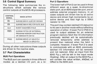
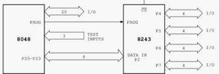
Port 2 Operations
The lower half of Port 2 can be used in three different ways:
as a quasi, bi-directional static port, as an 8243 expander port, and to address external program memory.
In all cases outputs are driven low by an active device and driven high momentarily by an active device and held high by a 50Kohm resistor to +5V.
The port may contain latched I/O data prior to its use in another mode without affecting operation of either.
If lower Port 2 (P2.0-P2.3 is used to output address for an external program memory fetch the I/O information previously latched will be automatically removed temporarily while address is present then restored when the fetch is complete.
However, if lower Port 2 is used to communicate with an 8243, previously latched I/O information will be removed and not restored.
After an input from the 8243 P2.0-P2.3 will be left in the input mode (floating). After an output to the 8243 P2.0-P2.3 will contain the value written, ANDed, or ORed to the 8243 port.
ポート2の動作
ポート2の下半分は、3つの異なる方法で使用できる:
準双方向スタティック・ポートとして、8243エクスパンダ・ポートとして、そして外部プログラム・メモリのアドレスとして。
すべての場合において、出力はアクティブ・デバイスによってLowに駆動され、アクティブ・デバイスによって瞬間的にHighに駆動され、+5Vへの50KΩ抵抗によってHighに保持される。
ポートは、他のモードで使用する前にラッチされたI/Oデータを含んでいても、どちらの動作にも影響しない。
下位ポート2(P2.0-P2.3)が外部プログラム・メモリ・フェッチ用のアドレス出力に使用される場合、アドレスが存在する間、以前にラッチされたI/O情報は自動的に一時的に除去され、フェッチが完了すると復元される。
ただし、下位ポート2が8243との通信に使用された場合、以前にラッチされたI/O情報は削除され、リストアされません。
8243からの入力後、P2.0-P2.3は入力モード(フローティング)のままとなる。
8243への出力後、P2.0-P2.3は8243ポートに書き込まれた値、ANDされた値、またはORされた値を含みます。
BUSポート
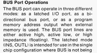
BUS Port Operations
The BUS port can operate in three different modes:
as a latched I/O port, as a bidirectional bus port, or as a program memory address output when external memory is used.
The BUS port lines are either active high, active low, or high impedance (floating).
The latched mode (INS, OUTL) is intended for use in the single chip configuration where BUS is not being used as an expander port.
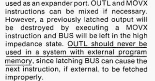
OUTL and MOVX instructions can be mixed if necessary.
However, a previously latched output will be destroyed by executing a MOVX instruction and BUS will be left in the high impedance state.
OUTL should never be used in a system with external program memory, since latching BUS can cause the next instruction,if external, to be fetched improperly.
BUS ポートの操作について
BUS ポートは3つの異なるモードで操作できます:
ラッチI/Oポートとして、双方向バスポートとして、外部メモリ使用時のプログラム・メモリ・アドレス出力として。
BUSポート・ラインは、アクティブ・ハイ、アクティブ・ロー、またはハイ・インピーダンス(フローティング)のいずれかである。
ラッチ・モード(INS、OUTL)は、BUSがエクスパンダ・ポートとして使用されないシングル・チップ構成での使用を意図しています。
OUTL 命令と MOVX 命令は必要に応じて混在させることができます。
ただし、MOVX 命令を実行すると、以前にラッチされた出力は破壊され、BUS はハイ・インピーダンス状態になります。
BUSをラッチすると、次の命令(外部命令である場合)が不適切にフェッチされる可能性があるため、OUTLは外部プログラム・メモリを持つシステムでは決して使用しないでください。
8243の各ポートの動作
8243 MCS-48 Expander 5-60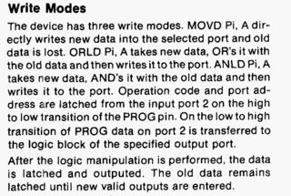
Write Modes
The device has three write modes. MOVD Pi, A dir-ectly writes new data into the selected port and old data is lost. ORLD Pi, A takes new data, OR's it with the old data and then writes it to the port. ANLD Pi, A takes new data, AND's it with the old data and then writes it to the port. Operation code and port ad-dress sire latched from the input port 2 on the high to low transition of the PROG pin. On the low to high transition of PROG data on port 2 is transferred to the logic block of the specified output port.
After the logic manipulation is performed, the data is latched and outputed. The old data remains latched until new valid outputs are entered.
書き込みモード
デバイスには3つの書き込みモードがある。MOVD Pi, Aは選択されたポートに新しいデータを直接書き込み、古いデータは失われます。ORLD Pi, A は新しいデータを取り、古いデータと OR してポートに書き込みます。ANLD Pi, A は新しいデータを取り、古いデータと AND してポートに書き込む。オペレーションコードとポートアドレスは、PROG端子のHighからLowへの遷移時に入力ポート2からラッチされる。PROG端子のロー→ハイ遷移でポート2のデータが指定された出力ポートの論理ブロックに転送される。
ロジック操作が実行された後、データはラッチされて出力されます。新しい有効な出力が入力されるまで、古いデータはラッチされたままです。
Read Mode
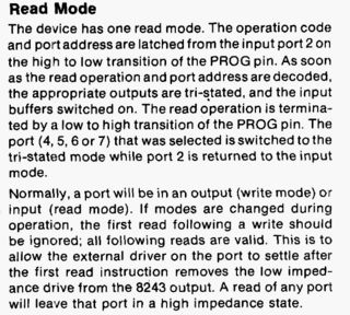
The device has one read mode. The operation code and port address are latched from the input port 2 on the high to low transition of the PROG pin.
As soon as the read operation and port address are decoded, the appropriate outputs are tri-stated, and the input buffers switched on. The read operation is termina-ted by a low to high transition of the PROG pin. The port (4, 5, 6 or 7) that was selected is switched to the tri-stated mode while port 2 is returned to the input mode.
Normally, a port will be in an output (write mode) or input (read mode). If modes are changed during operation, the first read following a write should be ignored; all following reads are valid. This is to allow the external driver on the port to settle after the first read instruction removes the low imped-ance drive from the 8243 output. A read of any port will leave that port in a high impedance state.
リード・モード
デバイスには1つのリード・モードがある。動作コードとポート・アドレスは、PROGピンのHighからLowへの遷移時に入力ポート2からラッチされる。
読み出し動作とポート・アドレスがデコードされるとすぐに、適切な出力が3ステー トされ、入力バッファがオンになります。読み出し動作は、PROG ピンのローからハイへの遷移で終了する。選択されたポート(4、5、6 または 7)はトライステート・モードに切り替わり、ポート 2 は入力モードに戻る。
通常、ポートは出力(書き込みモード)または入力(読み出しモード)になります。動作中にモードが変更された場合、書き込みに続く最初の読み出しは無視されるべきである。これは、最初の読み出し命令が 8243 出力から低インピーダンス・ドライブを除去した後、ポートの外部ドライバが落ち着くようにするためである。どのポートをリードしても、そのポートはハイ・インピーダンス状態になる。